
Ne5532 Circuit Diagram
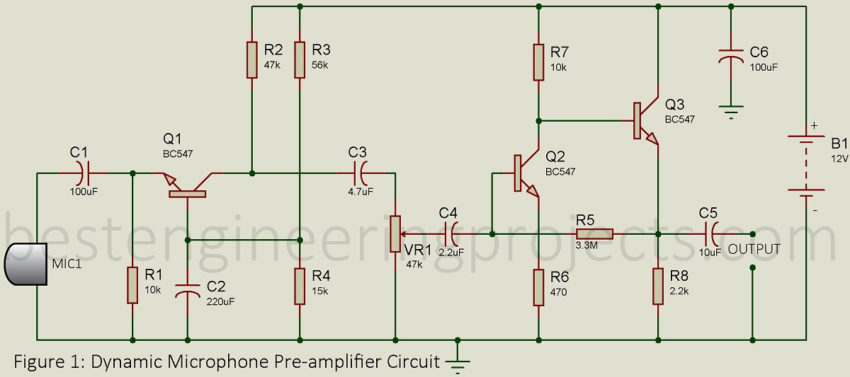
The microphone amplifier can work with two or three output electret microphones. Ne5532 headphone amplifier circuit diagram:

Tone Control Circuit Diagram With Pcb Layout Lm324 Tone
Circuit ne5532 there is no critical material on the opamp installed circuit.
Ne5532 circuit diagram. It compares with a most standard operational amplifier like 1458. Ne5532 op amp ic circuit diagram. Good sound quality is achieved through the use of radio components such as tantalum capacitors and the.
The ne5532 commonly used as a preamp and with very good performance. Riaa stereo preamplifier classic version based on ne5532 amplifier circuit design. Alternatively, you can also use lm833 on tl082.
Audio signals are received from electret mic and are sent to the ics input. Distortion effect circuit has low current consumption and works with 9v battery. Circuit design and pcb layout.
Also box, pcb is very stylish in printed circuit design. A circuit diagram also known as an electrical diagram elementary diagram or electronic schematic is a simplified conventional graphical representation of an electrical circuit. Mic preamp circuit for shure microphone.
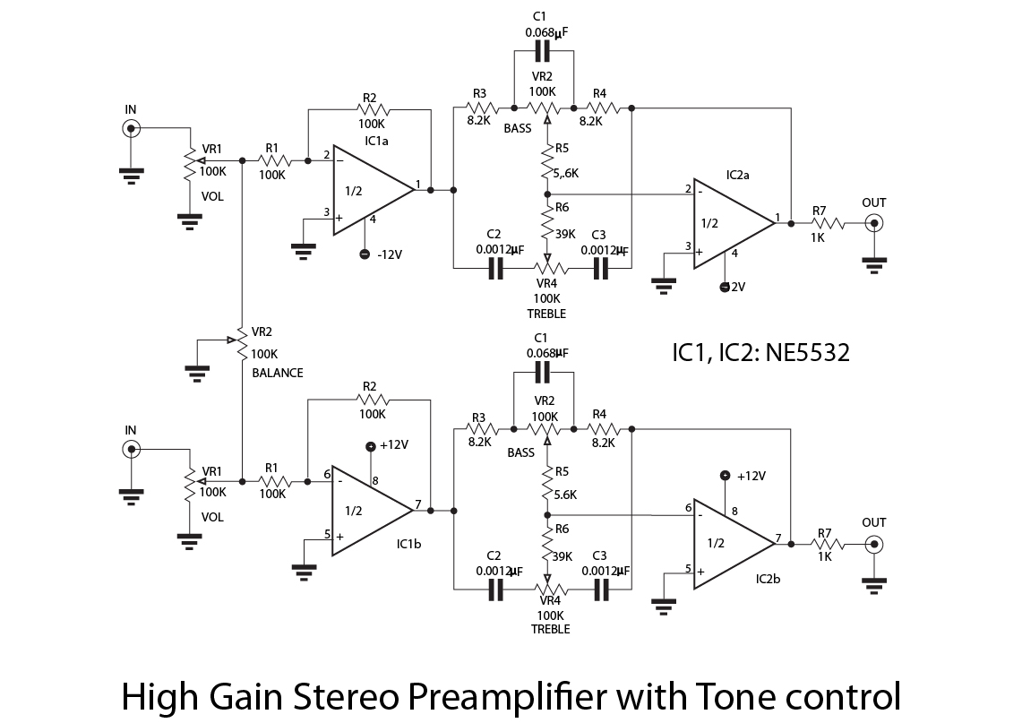
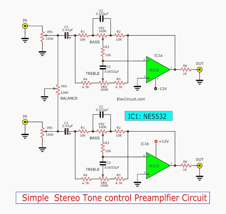
A ne5532 audio preamplifier circuit bass mid treble tone control circuits pre mic. A ne5532 audio preamplifier circuit diagram plotted by this system. Today, we will walk you into the introduction of the popular dual op amp ne5532, you will learn its pinout, features, application, circuit diagram and its differences with tl072 and more.
We also can use it in small power amplifier such as headphone amplifier. Audio circuits using the ne5532/4 audio circuits using the ne5532/34 the following will explain some of on semiconductors low noise op amps and show their use in some audio applications. Riaa equalization is actually a low pass filter having transition points at frequencies of 2122hz, 500hz.
The microphone amplifier schematic diagram and printed circuit board (pcb) were developed in easy eda online environment. 2 audio circuits using the ne5532/33/34 the following will explain some of philips semiconductors low noise op amps and show their use in some audio applications. What you have posted is power amplifier with a gain of 10 (r5 and r6 form a voltage divider for negative feedback).
Left part of the software interface is electronics template library, and the right part is canvas. The stereo riaa preamplifier circuit is based on ne5532. The ne5532 is a dual operational amplifier.
Q1 and q2 provide a higher current push. You can connect any audio source in the place of a microphone. All of them can be found on the market.
It shows better low noise performance. A ne5532 audio preamplifier circuit diagram plotted by this system scientific 5 bass mid treble tone control circuits projects using 4558 lf353 electro schema datasheet pre mic microphone 2 ch ic or pinout features nerdytechy universal preamplifiers 741 lm382 eleccircuit com how does amplifier work faq project 158 seekic. This op amp schematic is a typical application schematic.
A 18v battery is used as the primary source of power. Amplifier ne5532 preamp preamplifier volume tone control finished board dual ac 12v 18v audio power. Compared to most of the standard operational amplifiers, such as the 1458, it.
Ne5532 is a dual operational amplifier, designed with particular emphasis on performance in audio systems. Audio circuits using the ne5532/3/4 an142 1984 oct 2 august 1988 rev: This is the design diagram of 5 band graphic equaliser circuit build using operational amplifier chips, the ne5532 or lm833.
5 bass mid treble tone control circuits projects using ne5532 4558 lf353 electronic circuit projects circuit projects circuit the.

5 (bass mid treble) Tone control circuits projects using

Ne5532 Preamplifier Circuit Diagram / Hi Fi Riaa Phono

Ne5532 Preamplifier Circuit Diagram / Riaa Phono Preamps

*HELP* NE5532P Tone Control Circuit diyAudio

Pin on Vacuum tube
Ne5532 Preamp Circuit Breakers Wiring Diagram
Ne5532 Preamp Schematic


Simple 12V Low Pass Filter NE5532 Electronic Circuit
operational amplifier NE5532 OPAmp

Subwoofer Filter NE5532 Schematic PCB Electronic Circuit
Ne5532 Preamplifier Circuit Diagram / Riaa Phono Preamps

NE5532 High and Low Pass Output Filter Circuit Audio
+by+IC++NE5532x2.jpg)
IC NE5532 x2. Tone Control Stereo (basstreble
Ne5532 Preamplifier Circuit Diagram / Mono Preamp Based on

Ne5532 Preamplifier Circuit Diagram / Hi Fi Riaa Phono
5 (bass mid treble) Tone control circuits projects using
Ne5532 Power Amplifier Circuit Diagram Wiring Diagrams


NE5532 Class A Power Amplifier Electronic Circuit

5 (bass mid treble) Tone control circuits projects using
